Articles
Finned HVAC and Refrigeration Coils
1. Purpose
Finned HVAC and refrigeration coils are crucial components in systems designed to transfer heat. Their primary function is to maximize heat exchange between the heating fluid, refrigerant/coolant flowing through tubes and the surrounding air. This is achieved by incorporating fins, typically made of aluminum or copper, which significantly increase the surface area available for heat transfer. This enhanced surface area leads to more efficient heat transfer, improving the overall system performance.
2.Types of Fin Coils
Finned coils can be categorized based on several factors:
Cooling coils: Used in air conditioners and chillers to remove heat from air, causing it to cool and dehumidify.
Heating coils: Utilized in furnaces, heating systems and heat pumps to transfer heat to air, warming it up.
Condenser coils: Found in refrigeration systems, responsible for releasing heat from the refrigerant to the surrounding environment.
Evaporator coils: Integral parts of refrigeration systems, absorbing heat from the environment to cool a space or product.
3.Applications:
Fin HVAC and refrigeration coils have a wide range of applications in various settings, including:
• Residential: Homes, apartments, condominiums (HVAC systems).• Commercial: Office buildings, shopping malls, schools, hospitals (HVAC systems).
• Industrial: Factories, warehouses, manufacturing plants (industrial process cooling, heating).
• Automotive: Car air conditioning and heating systems.
• Food and beverage: Refrigeration systems for food preservation and storage.
4. Design and Construction:
• Coil size and capacity: Determined by the required heat transfer rate for the specific application.• Fin spacing and geometry: Optimized to balance airflow resistance and heat transfer efficiency.
• Tube arrangement: Can be staggered or in-line, impacting airflow patterns, heat transfer and air static pressure.
• Coil circuiting: Designed to optimize heat transfer, maintain appropriate fluid velocity, minimize pressure drop,
and ensure even distribution across all tubes.
• Material selection: Based on factors like operating pressures, temperatures, corrosion resistance, and cost.
Water Coils. There are two types of water coils: Heating and Cooling Water Coils.
Heating Water Coils (Hot Water Coils) Primary Function: To heat air using hot water.
Applications: Space Heating: Used in air handling units (AHUs), fan coil units (FCUs), unit heaters, and cabinet heaters connected to a boiler system.
Reheat coils: In Variable Air Volume (VAV) terminal boxes to warm up cooled air before it enters a specific zone, allowing for better temperature control.
Pre-heating coils: Sometimes used to temper very cold outside air, though steam is often preferred for extremely low temperatures due to freeze concerns if not properly designed/controlled.
Residential Hydronics coils: Used in air handlers paired with a boiler for forced-air heating.
Design & Construction:
Fluid: Hot water, typically supplied from a boiler at temperatures ranging from perhaps 120°F to 200°F (approx. 49°C to 93°C), depending on the system design.
Tubes: Usually copper. Diameter and wall thickness depend on flow rates and pressure.
Fins: Typically aluminum, sometimes copper. Fin spacing (Fins Per Inch - FPI) is optimized for heat transfer and air pressure drop, often in the range of 8-14 FPI.
Rows: Commonly designed with 1 to 4 rows of tubes deep, sufficient for typical heating loads.
Circuiting: The path the water takes through the coil (e.g., single pass, multi-pass) is designed to ensure adequate water velocity for good heat transfer while managing water pressure drop. Often designed for counter-flow or cross-flow heat exchange.
Performance: Selection depends on required heating capacity (BTU/h), airflow (CFM), entering air temperature (EAT), entering water temperature (EWT), and either the desired leaving air temperature (LAT) or water flow rate (GPM).
Cooling Water Coils (Chilled Water Coils) Primary Function: To cool and dehumidify air using chilled water.
Applications: Space Cooling & Dehumidification: The primary cooling component in large AHUs and FCUs connected to a central chiller plant. Common in office buildings, hospitals, universities, hotels, and industrial facilities.
Process Cooling: Used in specialized AHUs for industrial processes requiring controlled temperature and humidity.
Design & Construction:
Fluid: Chilled water, typically supplied from a chiller at temperatures around 42°F to 45°F (approx. 5.5°C to 7°C). Tubes & Fins: Similar materials to heating coils (copper tubes, aluminum/copper fins). Rows: Significantly deeper than most heating coils, often ranging from 3 to 8 rows (or even more). This increased depth provides the necessary surface area for both sensible cooling (lowering the air temperature) and latent cooling (removing moisture/dehumidification). Dehumidification & Drain Pan: As air cools below its dew point, water vapor condenses on the cold fin surfaces. A drain pan (typically stainless steel, galvanized steel, or polymer) is mandatory beneath the coil to collect this condensate, which must then be drained away via a properly trapped drain line. Circuiting: Often uses counter-flow arrangements (water flows in the opposite direction of airflow) to maximize heat transfer efficiency. Circuiting is carefully designed to balance heat transfer with acceptable water pressure drop.
Fin Design: Fin spacing (often 8-14 FPI) and fin type (e.g., wavy, louvered) are selected to enhance heat transfer and manage moisture. Some designs may aim to prevent condensed water from being "carried over" into the ductwork at high air velocities. Performance: Selection is complex, involving airflow (CFM), entering air conditions (both dry-bulb temperature and wet-bulb/humidity), entering water temperature (EWT), required leaving air conditions, and total cooling load (sensible + latent BTU/h), alongside water flow rate (GPM)
Glycol heating coils:
Glycol heating coils essentially the same type of heat exchanger as water coils (finned tubes carrying fluid to heat or cool air), but they circulate a mixture of glycol and water instead of just water. The primary and most crucial reason for using a glycol solution (typically ethylene glycol or propylene glycol) is freeze protection.
Freezing water inside a coil's tubes can cause them to expand and burst, leading to significant damage and downtime. Using a glycol mixture lowers the freezing point of the fluid, protecting the coils and system components.
Glycol Cooling Coils:
Glycol cooling coils are the same type as cooling water coils. They fanction to cool and dehumidify air using a chilled glycol/water solution.
Applications: Used in AHUs and fan coil units connected to a chiller, particularly when: Freeze protection is needed due to cold entering air or ambient conditions. The application requires fluid temperatures near or below 32°F (0°C) (e.g., specialized process cooling, low-temperature dehumidification). The chiller itself requires freeze protection for its loop.
Design Considerations of Glycol Coils: Reduced Heat Transfer: Glycol has poorer heat transfer properties than water. To achieve the same heating capacity as a water coil, a glycol heating coil typically needs to be larger (more surface area/rows), have a higher fluid flow rate (GPM), or operate with higher entering fluid temperatures. Increased Viscosity: Glycol solutions are more viscous than water, increasing the pressure drop through the coil and requiring more pump energy. Construction: Similar to water coils (copper tubes, aluminum/copper fins). Selection depends on heating load, airflow, air temperatures, fluid temperatures, flow rate, and the specific type and concentration of glycol used.
Steam Coils: Steam is a potent heating medium due to the large amount of energy (latent heat) released when it condenses. There are two primary designs for steam coils:
Standard Steam Coils:
These typically have a simpler construction where steam enters a header, flows through the tubes, condenses, and the resulting condensate exits. They work well for many heating applications, especially where the entering air is always above freezing or when the coil operates in an on/off fashion (fully open or fully closed steam valve). However, if you try to control temperature by modulating (partially closing) the steam valve when handling air below freezing (32°F or 0°C), the reduced steam pressure and flow can lead to uneven heating, poor condensate drainage, and subsequent freezing and bursting of the tubes.
Steam Distributing Coils (Non-Freeze / Freeze-Resistant Type):
These coils feature a clever "tube-within-a-tube" design. Steam first flows down a smaller inner tube that runs the length of the main outer tube (the one with fins). The steam exits the inner tube near the far end and flows back through the annular space between the inner and outer tube. This design ensures steam is distributed more evenly along the entire length of the coil, even under low load (modulated) conditions. It promotes better condensate drainage back towards the header. This significantly reduces the risk of condensate freezing and damaging the coil when handling entering air temperatures below freezing while allowing for modulated temperature control. Application: Pre-heater Coils: One critical application, especially for Steam Distributing Coils, is as pre-heater coils. These are often the very first component in an air handling unit's intake section designed to handle 100% cold outdoor air (makeup air). Their job is to raise the temperature of potentially sub-freezing outdoor air before it reaches downstream components like filters (which can get blocked by ice), chilled water cooling coils (which could freeze), or dampers. By tempering the air, pre-heater coils protect equipment and allow the rest of the HVAC system to manage heating or cooling more effectively. Because they directly face potentially very cold air and often need to modulate steam flow to maintain a set discharge temperature, Steam Distributing (Non-Freeze type) coils are the standard choice for steam pre-heating applications due to their freeze-resistant design.
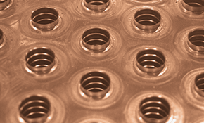
Fin type:
Plate fins: fins mechanically bonded to the tubes(tubes expended in fins), offering a compact design. The fins can be:Flat:
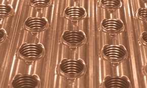
Wavy:
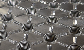
Star:
Spinefin: Round tubes with spines or pins attached, suitable for high-temperature applications.
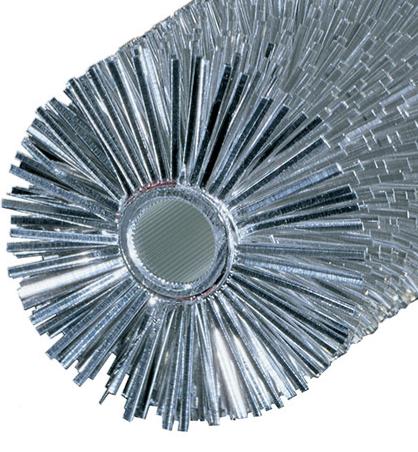
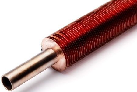
Helical (Spiral) fins:
Fin attachment methods:
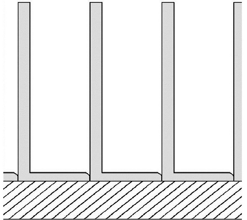
• Mechanical bonding:Edge tension wound:
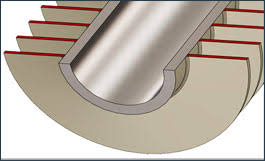
L-foot attachment:
• Extruded fins:
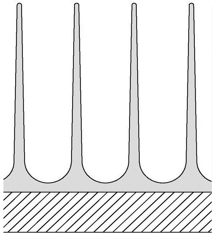
• Brazing: Creates a strong and durable bond between fins and tubes using a high-temperature filler metal.
• Welding: Employed for specific applications and materials requiring a permanent joint.
Thermal Calculation of Cooling Water/Glycol Helical Finned Coils.
Cooling coils are basically fin and tube heat exchangers used in any air conditioning installations. The cooling media is usually water from 42 F, also Ethylene or Propylene glycol water solutions of various concentrations can be used as the cooling media. Cooling fluid runs in tubes and air runs over fins. Low coolant temperature could result in a coil fin surface temperature that is below dew point temperature of air going through finned surface of a coil, which leads to condensation of moisture in air. The condensation in cooling coils complicates design and selection of cooling coils comparing to heating coils, because we have to account latent heat which is necessary to condense moisture in air. In this case the coil is Wet. When no condensation happens during cooling down air passing through a coil, the coil is Dry. The program considers a coil -Wet, when at least one of two conditions is met: the relative humidity of air is more the 30% and/or Dew Point Temperature of incoming air is more than Entering Water/Glycol Temperature.
There are two methods of calculating heat transfer load in heat exchangers: LMTD and NTU.
The “Logarithmic Mean Temperature Difference “(LMTD) is a logarithmic average of the temperature difference between the hot and cold streams at each end of the heat exchanger. The larger the LMTD, the more heat is transferred.
LMTD method works very well for dry coil runs (one-phase streams), but it is very inaccurate for two-phase streams, in our case – air and moisture in the air, which needs to be condensed. To use LMTD method, we have to know all four temperatures for both steams. Usually we either know or assume outlet temperatures. Then we calculate LMTD with a correction factor (derived as per geometry of heat exchanger and directions of both streams), corrected LMTD or CLMTD. Mass flow of at least one stream is known. Knowing the temperature difference, mass flow and specific heat for the stream, we can calculate total heat transfer rate for the process, overall heat transfer coefficient and heat transfer area of the coil. Based on this data the program is trying to match the calculated coil heat transfer area to the given or assumed coil geometry (given heat transfer area), gradually changing outlet temperature of the stream in question in a loop until the heat transfer areas, given and calculated are matched.
The Effectiveness-NTU method takes a different approach to calculating heat exchange analysis by using three dimensionless parameters: Heat Capacity Rate Ratio (HCRR), Effectiveness (ε), and Number of Transfer Units (NTU). The relationship between these three parameters depends on the type of heat exchanger and the internal flow characteristics.
The NTU method is useful when minimum data is provided for calculating heat transfer. In our case: the amount of moisture is to be condensed during the process and additional heat load which is necessary to do so and outlet dry and wet bulb temperatures are unknown.
First, the program calculates Heat Capacity Rate for each stream in the process. Then it selects the minimum and maximum Heat Capacity Rates for both steams. Usually the stream with a bigger temperature difference has minimum capacity rate. HCRR is calculated as a ratio between minimum and maximum capacity rates. NTU is calculated as heat transfer area of a coil multiplied by overheat transfer coefficient and divided by minimum capacity rate.
Effectiveness (ε) can be derived from graphs or equations for certain types of heat exchangers using NTU and HCRR data.
Heat transfer load for a cooling coil is calculated as maximum possible heat transfer load for Minimum Capacity Rate stream multiplied by Effectiveness (ε). Effectiveness (ε) value is in the range between 0 and 1.
F & T Steam Traps.
F & T traps are the common trap type used for process applications: S&T heat exchangers, steam generators, waters heaters, heating coils, etc.
F & T traps can handle both light and heavy condensate loads at different pressures and temperatures.
F & T steam trap basically is normally closed mechanical valve, where the valve opens when condensate enters the trap’s chamber, lifts a float, and at that moment the condensate discharges and continues to discharge in a piping system while the float is up. When the trap is filled with steam, the internal pressures in the chamber equalizes and float drops down, closing the valve until the steam in the trap’s chamber turns to condensate.
Thermostatic element (air vent) in the trap is to vent air out of trap.
The air vent is normally open and its function is to pass air and other non- condensable gases into the return line. Once steam arrives at the trap, this element snaps shut preventing steam from passing into the return lines, and its job is finished until the next cycle.
To size properly F & T trap, the following conditions must be known:
• operating inlet pressure
• operating outlet pressure or back pressure
• differential pressure (i.e. the difference between the inlet pressure and the outlet pressure)
• flow capacity of condensate to be removed.
• type of steam system: Constant (steam flows continuously) or Modulating (steam flow controls by temperature or pressure control valve).
If the flow rate is unknown, condensate flow rate can be simply estimated by means of the calorific power of the heating apparatus expressed in BTU/hr and by using the following formula: Condensate Flow Rate lb/hr = BTU Rating (in millions)/100.
Every trap is sized with safety factor applied to a condensate flow rate needed to be discharged.
Depending upon manufacturer’s requirements and a particular application, the safety factor might be from 1.5 to 3.
The difference between a trap's inlet (primary) pressure and back pressure is called the 'differential pressure' or ‘pressure differential’. The 'back pressure' is the pressure just downstream of the steam trap. In other words, back pressure is the outlet or secondary pressure of the trap. If the condensate is discharged to the atmosphere just after the trap, the back pressure is considered to be 0 psig. Even if the trap discharges to atmosphere, restrictions in the downstream piping such as elbows, tees and valves may add back pressure.
Vertical lifts (risers) in the condensate piping add back pressure in the form of hydraulic head. A rule of thumb is that every foot of rise in the condensate line after the steam trap equals ½ psig backpressure on the steam trap discharge. If the condensate discharges into a flash tank and the flash tank pressure increases, the back pressure increases correspondingly.
The maximum allowable back pressure for disc traps is generally 50% to 80% of the inlet of inlet pressure. Mechanical traps on the other hand, have a relatively back pressure of over 90%. A high percentage of steam trap applications will have pressure at the discharge side of the steam trap from the condensate return system. The back pressure may be unintentional or deliberately produced by the design or by the operation of the condensate return system. Unintentional back pressure is caused by a static pressure or rise in condensate piping after the steam trap. The main condensate lines are typically installed at a high elevation and located above the steam traps; therefore, it is necessary to pipe the condensate from the steam trap location up to the higher condensate mains. Undersized condensate lines are another factor that can cause backpressure on the steam trap that must be considered when sizing steam traps. Condensate lines need to be sized for two-phase flow (condensate and flash steam). Another factor that increases condensate line pressure is failed steam traps blowing steam in a condensate line that was not designed for a high volume of steam.
Formed Heads. Pressure on Concave Side
Introduction:
Formed heads are crucial components in pressure vessels, serving as the end closures. They are designed to withstand internal or external pressure. The selection of a specific head type depends on factors like pressure, temperature, material, and manufacturing feasibility. This article discusses the types of formed heads and the principles of calculations as per ASME Section VIII, Division 1 (UG-32 and Appendix 1-4).
Types of Heads:
Formed heads come in various shapes, each tailored for specific applications. Here are the common types:
- Hemispherical Heads: These heads offer the highest strength-to-thickness ratio, making them ideal for high-pressure applications.
- Ellipsoidal Heads: Ellipsoidal Heads are a popular choice due to their balance of strength and manufacturability. The 2:1 ratio refers to the major to minor axis ratio.
- Torispherical Heads: Commonly used for moderate pressure applications. They consist of a spherical dish and a toroidal knuckle.
- Conical Heads: Employed when a transition in diameter is needed, often used in conjunction with cylindrical shells.
- Toriconical Heads: A toriconical head is a type of pressure vessel head that is a combination of a torispherical head and a conical head. The toriconical head is a stronger and more efficient design than the torispherical head.
- Flat Heads: Suitable for low-pressure applications, typically requiring substantial reinforcement.
The design of formed heads under pressure is governed by codes such as ASME Section VIII, Division 1. Specifically, UG-32 and 1-4 provide guidelines for calculating the required thickness of heads under internal pressure. UG-32 outlines the formulas for calculating the minimum required thickness of heads of revolution, including hemispherical, ellipsoidal, torispherical and toriconical heads. The calculations are based on factors like design pressure, material allowable stress, and head geometry.
Key Concepts in UG-32:
- Design Pressure (P): The maximum pressure the vessel is designed to withstand.
- Allowable Stress (S): The maximum permissible stress for the material at the design temperature.
- Head Geometry: The dimensions of the head, such as inside radius (L), knuckle radius (r), and straight flange length.
Appendix 1-4: Ellipsoidal Heads
Paragraph 1-4 specifically addresses the design of ellipsoidal heads. It provides formulas and guidelines for determining the required thickness based on the 2:1 ellipsoidal ratio and the design conditions.
Key Concepts in Appendix 1-4:
- 2:1 Ellipsoidal Ratio: The ratio of the major axis to the minor axis of the ellipse.
- Thickness Calculation: Formulas are provided to calculate the minimum required thickness, considering the design pressure and material properties.
General Calculation Principles:
The general formulas involve calculating the required thickness (t) based on the design pressure (P), allowable stress (S), and geometric factors. The formulas vary depending on the head type. For instance, for a hemispherical head:
t = (P * L) / (2 * S * E - 0.2 * P)
Where:
- t = minimum required thickness
- P = design pressure
- L = inside spherical radius
- S = allowable stress
- E = joint efficiency
For ellipsoidal and torispherical heads, the formulas are more complex, incorporating factors like knuckle radius and dish radius. Consult ASME Section VIII, Division 1 for the specific formulas and requirements.
Disclaimer: This information is for general knowledge and educational purposes only.